 |
ME 405: Mechatronics Portfolio
|


|
|
ME 405: Mechatronics Portfolio
|
|
This page serves as a main page and directory for my ME 405 portfolio. This portfolio contains documentation for all code generated for lab and lecture assignments for Mechatronics over the course of the Winter 2021 quarter.
Vendotron.py is a vending machine FSM capable of accepting and storing payment details, dispensing beverages, and calculating change.
Vendotron.py source code-- https://bitbucket.org/MilesYoung/me305_me405_labs/src/master/ME%20405/Lab%201/Vendotron.py
ReactionTest.py is a reaction time test featuring a built in LED and button on the NUCLEO microcontroller.
ReactionTest.py source code-- https://bitbucket.org/MilesYoung/me305_me405_labs/src/master/ME%20405/Lab%202/ReactionTest.py
ButtonUI.py is the PC user front-end program that works in conjuction with the NUCLEO data collection program Button_main.py to collect and plot voltage response data for a built-in button on the NUCLEO MCU.
ButtonUI.py source code-- https://bitbucket.org/MilesYoung/me305_me405_labs/src/master/ME%20405/Lab%203/ButtonUI.py
Button_main.py source code-- https://bitbucket.org/MilesYoung/me305_me405_labs/src/master/ME%20405/Lab%203/Button_main.py
example .csv, Button Voltage vs. Time-- https://bitbucket.org/MilesYoung/me305_me405_labs/src/master/ME%20405/Lab%203/Button%20Voltage%20vs.%20Time.csv
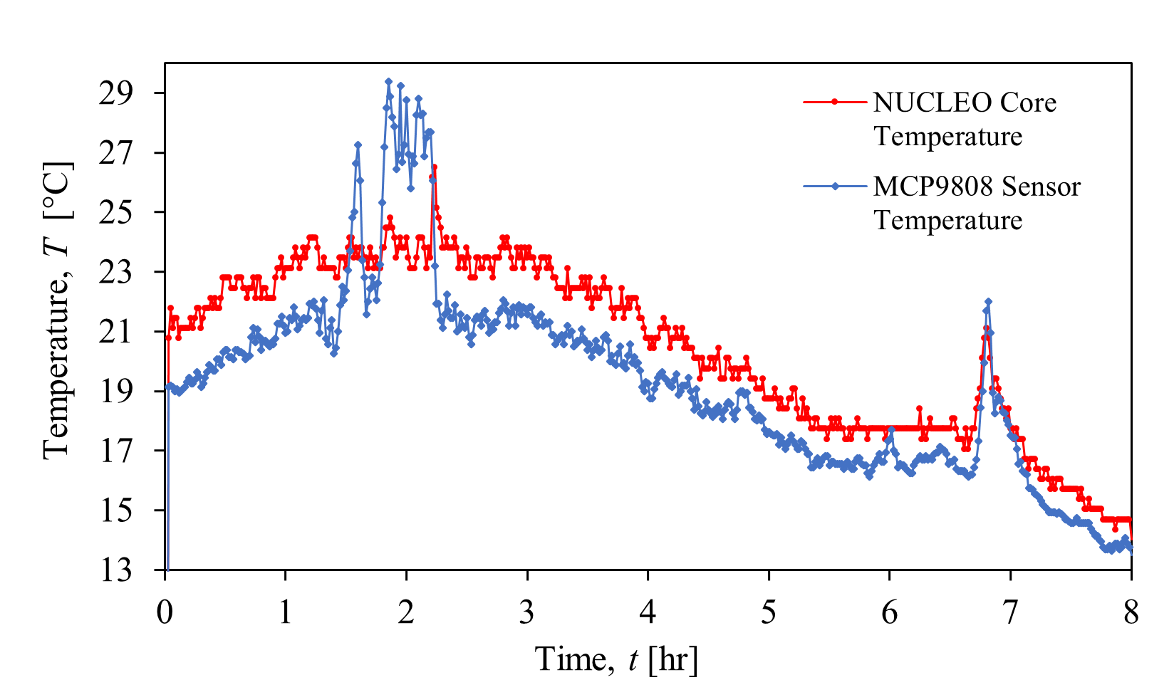
The Adafruit MCP9808 temperature sensor breakout board I2C communication class mcp9808_young.py is used in main_young.py in conjunction with the built-in ADC core temperature reading function of the NUCLEO to record internal and external temperature measurements every minute (approximately). These measurements, along with the time in milliseconds since the beginning of data collection, are written to a new line in file Temperature.csv on the NUCLEO.
main_young.py source code-- https://bitbucket.org/MilesYoung/lab-4/src/master/main_young.py
mcp9808_young.py source code-- https://bitbucket.org/MilesYoung/lab-4/src/master/mcp9808_young.py
Example Temperature.csv-- https://bitbucket.org/MilesYoung/lab-4/src/master/Temperature.csv
The measurements in this plot were taken between the hours of 9:30 am and 5:30 pm on a sunny February day in my backyard in San Luis Obispo. Observable spikes align with times at which the MCP9808 and/or NUCLEO were exposed to direct sunlight. All other measurements were taken in moderate shade.
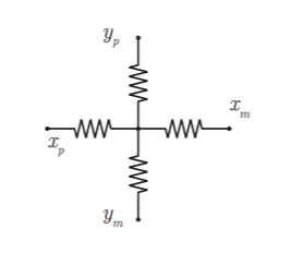
this resistive touch panel driver class from TouchDriver.py can be used to determine a point of contact on the panel.
TouchDriver.py source code-- https://bitbucket.org/MilesYoung/me305_me405_labs/src/master/ME%20405/Lab%207/TouchDriver.py
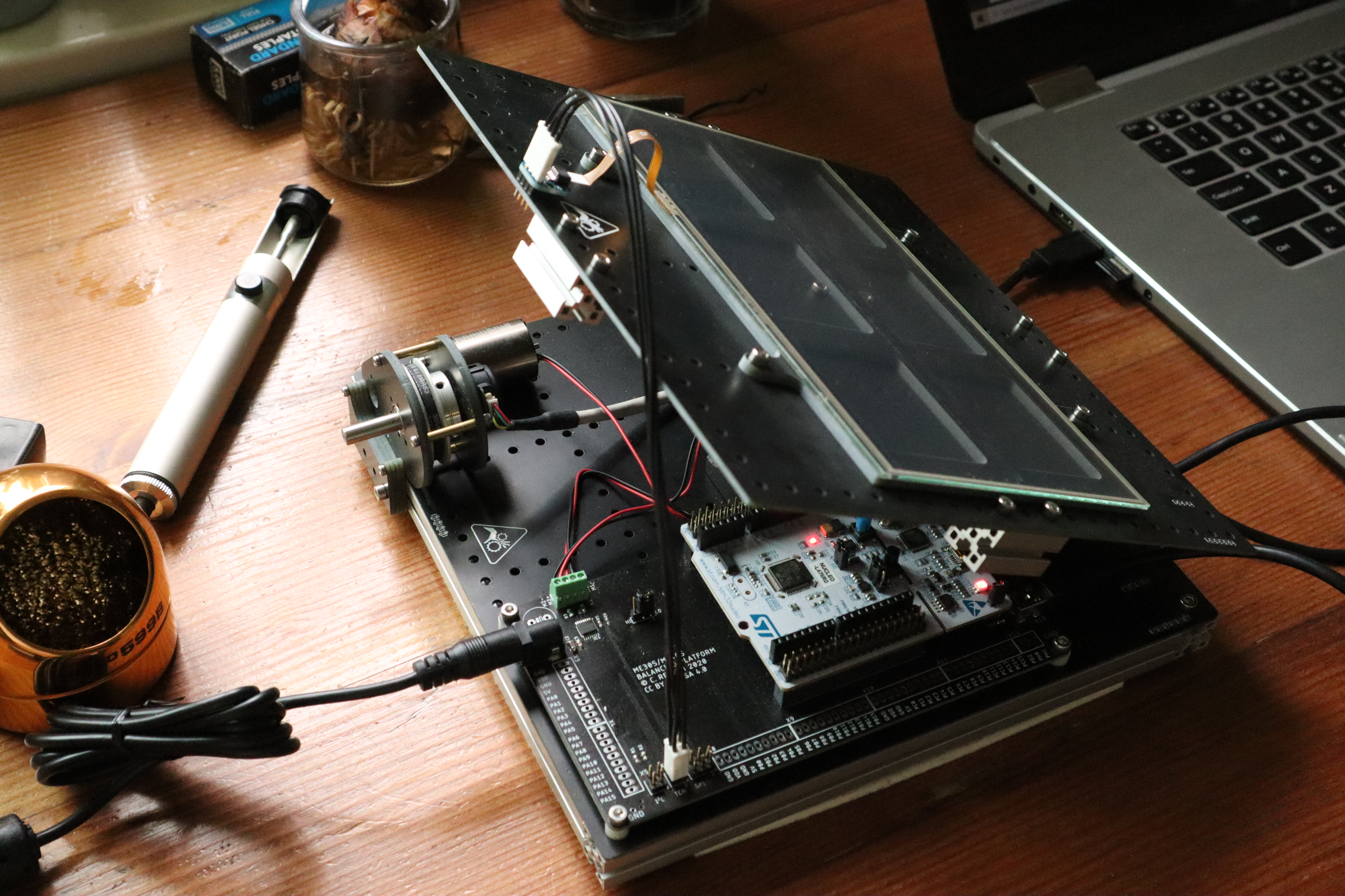
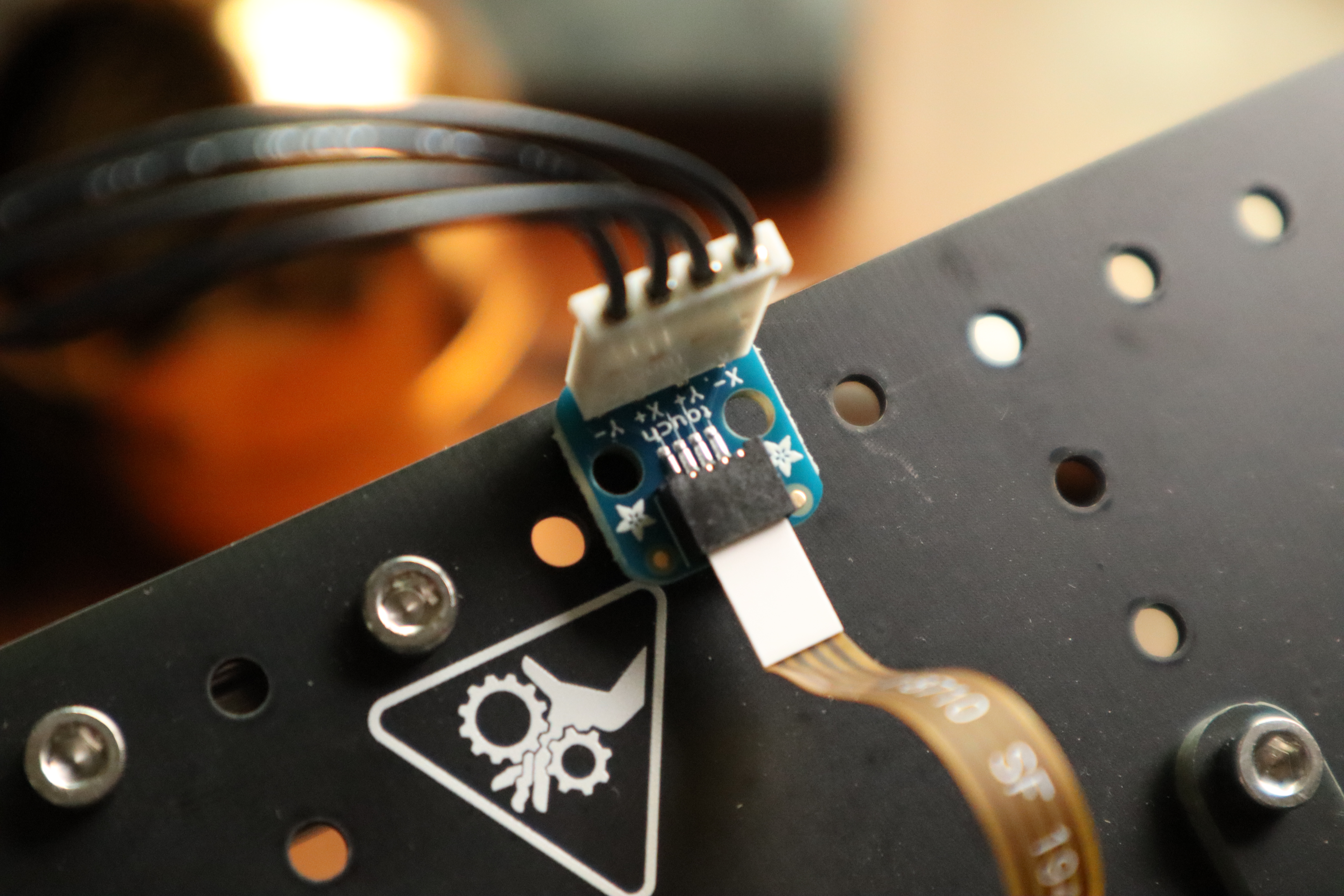
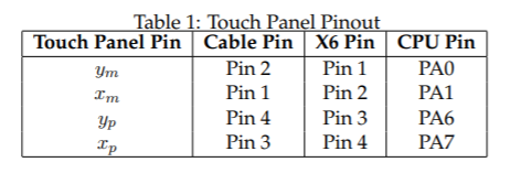
Hardware and Setup
Some hardware assembly was required in order to allow the touch panel sensor to interface with the NUCLEOL476RG microcontroller. I soldered a double-header pin on to the platform of the system and then soldered an Adafruit FPC breakout board to these pins. This breakout board adapted the conductive output strip from the panel to four individual output pins which could be connected to the main board through a 4-channel cable.
Test Code and Results
In order to ensure that this code will function cooperatively with other drivers and scripts which will be running simultaneously to control the platform's balance, I needed to write test code to measure the linear range and average runtime of each method. To calibrate the scaling factor used in the x and y scanning methods, I measured the maximum and minimum ADC readings for each respective axis and visually determined their corresponding position. From these measurements, I determined the following equations:
x scaling factor
y scaling factor
where the center list containing center coordinates of the form [x_center,y_center]. These coordinates were measured in a similar fashion to that of the boundaries of the touch panel linear region. I found the median value within each set of boundaries and measured the corresponding location visually.
To determine the average run speed of each method, I emplemented the following code into the script using an 'if name =="__main__"' block, shown below:
For which an example output in the REPL might be:
To prepare for the upcoming BalanceBot term project, my teammate and I updated our ME 305 motor and encoder driver classes, written in MotorDriver.py and EncoderDriver.py respectively. Updates to the motor driver include the implementation of an external interrupt triggered by a fault pin, intended to prevent damage to the motors in the case of current overloads from collisions. Updates to the encoder driver include new methods for calculating angles and speeds in radians or radians per second, respectively. MotorDriver.py source code-- https://bitbucket.org/MilesYoung/lab-4-term-project/src/master/Lab09/MotorDriver.py EncoderDriver.py source code-- https://bitbucket.org/MilesYoung/lab-4-term-project/src/master/Lab09/EncoderDriver.py